With the rapid expansion of large AI models and the scale of computing clusters, AI data centers are imposing stringent performance and reliability requirements on lithium-ion battery backup and energy storage systems. As the central control hub of the lithium backup power unit, the Battery Management System (BMS) executes core functions including cell status monitoring, charge/discharge protection, cell balancing, fault alerting, and safety management. Consequently, the reliability of its internal components directly dictates the power continuity and operational safety of computing infrastructure. Leveraging its proprietary magnetic core material formulations and 25 years of technical expertise in the inductor industry, Codaca has introduced a dedicated series of power inductors tailored for AI data center backup BMS applications. These components directly address key engineering challenges—such as bidirectional high-current surges, high-frequency ripple interference, continuous year-round operation, and severe ambient temperature fluctuations in data center environments—thereby providing high-reliability magnetic solutions for AI data center energy storage and backup power architectures.
1. New Application Challenges Facing Backup BMS in AI Data Centers
AI server GPU computing loads exhibit millisecond-level, violent fluctuations, with instantaneous power surges reaching several times the steady-state load. Relying solely on traditional centralized UPS architectures makes it economically and operationally challenging to match these dynamic load characteristics. Consequently, lithium-battery Backup Battery Unit (BBU) solutions have emerged as a primary technical architecture for newly constructed AI data centers (AIDCs).As the safety core of the lithium-ion backup power unit, the Battery Management System (BMS) extensively incorporates power and signal inductors across its internal DC-DC power conversion modules, active cell balancing circuits, and signal filtering networks. Inductor performance defects or component failures can directly induce BMS power supply anomalies, cell balancing malfunctions, and SOC estimation errors. Under extreme operating conditions, these issues can trigger emergency battery protection shutdowns, ultimately resulting in server outage and computing service disruption.
Compared with ordinary industrial energy storage BMS, backup BMS for AI data centers present several unique design pain points:
(1) Bidirectional Transient High-Current Surges: Backup power systems are required to deliver high-power output over short durations and assist in peak shaving. Under severe di/dt load transients, inductors must withstand large pulsating current amplitudes and high peak surges. Should magnetic core saturation occur, it can trigger BMS power supply failure and false protective trip events.
(2) Continuous Year-Round Operation: With data centers operating over an 8-to-10-year lifecycle, power inductors endure continuous load conditions throughout their operational life. This places stringent demands on DCR copper loss, magnetic core loss, and long-term thermal rise stability, requiring absolute freedom from aging-induced performance drift or thermal failure.
(3) Severe EMI Environments in High-Density Server Racks: High-density server cabinets house numerous SiC/GaN switched-mode power supplies that generate intense high-frequency switching noise. Within the BMS, Analog Front-End (AFE) sampling and voltage/current sensing circuits handle highly sensitive signals. Magnetic flux leakage from unshielded or poorly shielded inductors can induce interference on these sampling paths, leading to calculation offsets in State of Charge (SOC) and State of Health (SOH) that ultimately compromise battery safety.
(4) Wide-Temperature On-Board Operating Conditions: Localized thermal hotspots frequently develop across BMS printed circuit boards (PCBs), requiring onboard components to maintain stable electrical parameters across a broad temperature range of -40°C to +125°C. Crucially, power inductors must exhibit minimal saturation current derating under elevated operating temperatures to ensure reliable circuit performance.
(5) High-Power-Density Hardware Layouts: Server rack space is at a premium, driving continuous increases in BMS controller board integration density. Consequently, power inductors must combine high current-carrying capacity with miniaturized surface-mount packaging, while simultaneously satisfying stringent PCB-level mechanical stress and vibration resistance standards.
2. The Core Role of Inductors in Backup BMS Systems for AI Data Centers
Within lithium-battery backup BMS architectures for AI data centers, power inductors are principally deployed across power conversion stages, cell balancing circuits, and signal filtering subcircuits. The operational stability of each stage directly impacts the overall reliability and safety of the backup power system.
(1) Main-control DC-DC power circuit
The BMS mainboard MCU, Analog Front-End (AFE) ICs, sampling operational amplifiers, and communication interface transceivers rely on multiple stable low-voltage power rails generated from the main battery bus voltage via Buck/Boost DC-DC converters. Serving as core energy storage and filtering components, power inductors deliver clean, stable power rails to BMS control units. Should an inductor saturate or exhibit abnormal power loss, it can destabilize the primary BMS power supply, leading directly to a loss of critical battery monitoring and protection functions.
(2) Active balancing circuit
Due to the high cell count within AI backup battery modules, cell consistency gradually degrades over prolonged charge and discharge cycles. Inductor-based active balancing topologies rely on energy storage inductors to facilitate energy transfer between individual battery cells. The parameter stability of these inductors directly governs balancing efficiency and accuracy, ensuring complete capacity utilization across the entire battery pack, mitigating cell overcharge and overdischarge risks, and extending overall energy storage battery service life. Common active cell balancing topologies include direct transformer-based schemes (bidirectional flyback converters), switch matrix with transformer architectures, and non-isolated bidirectional buck-boost inductor-based balancing circuits. While the former two topologies rely on transformers to execute energy transfer between individual cells, bidirectional buck-boost balancing operates on standard Buck-Boost circuit principles, providing a simpler and more straightforward hardware implementation. The operating principle of buck-boost active balancing relies on transferring charge directly between adjacent battery cells rather than moving energy across disparate locations within the pack. This design significantly simplifies balancing circuit complexity while fully leveraging the simultaneous operation of multiple balancers to redistribute charge throughout the entire battery string.
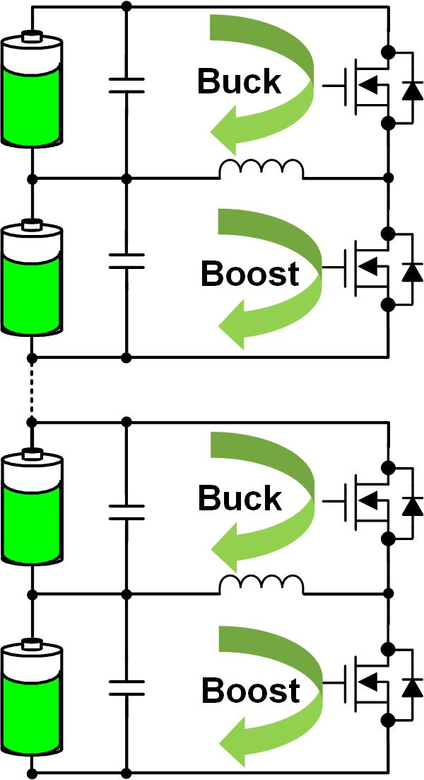
Figure 1. Bidirectional buck-boost active balancing topology
As shown in Figure 1, one bidirectional buck-boost balancer is configured on each pair of cells. Through buck/boost balancing modes, it provides bidirectional charge transfer between two adjacent cells, ultimately achieving consistency in the capacity of all cells. In buck balancing mode, the active balancer transfers energy from the upper cell to the lower cell; in boost balancing mode, it transfers energy from the lower cell to the upper cell.
(3) EMI/EMC filtering circuit
The main battery charge/discharge bus exhibits high-frequency switching ripple and transient noise spikes. Differential-mode inductors combined with capacitors form LC filtering networks that suppress current spikes induced by bidirectional power switching, reduce noise coupling into BMS sampling circuits, safeguard voltage and current sensing accuracy, and minimize cumulative State-of-Charge (SOC) estimation errors. Common-mode inductors are deployed to suppress common-mode noise along power lines, blocking external electromagnetic noise from coupling into the BMS while simultaneously preventing internal BMS switching noise from radiating to adjacent equipment.
3. CODACA Provides High-Reliability Inductors for Backup BMS Systems in AI Data Centers
To address the unique operational requirements of AI data center backup battery management systems (BMS), Codaca optimizes its inductors across multiple dimensions, including magnetic core material formulations, winding architecture, and reliability design. Engineered for various power levels within AI backup BMS circuits, Codaca provides a comprehensive matrix of field-proven products:
(1) High current power inductors
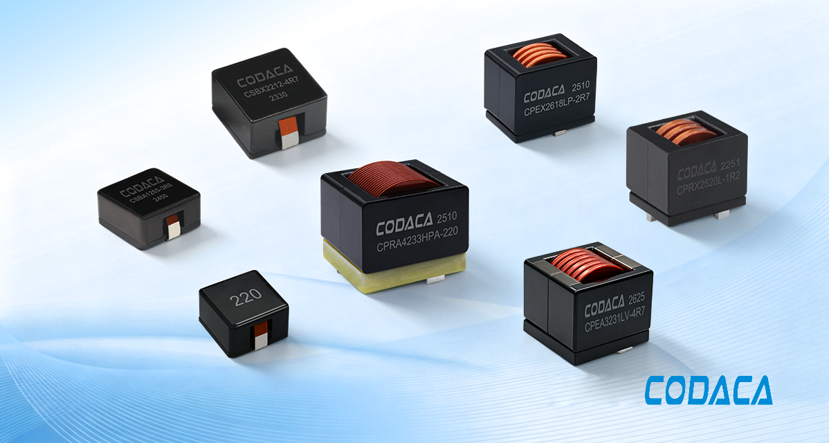
Codaca's proprietary high-current power inductors feature low-loss magnetic core materials and flat-wire coil winding designs, delivering ultra-low core losses and excellent soft-saturation performance. When subjected to instantaneous high-current surges, the inductance exhibits a smooth, gradual roll-off rather than a precipitous drop, effectively preventing complete core saturation failure during abrupt load current spikes. Featuring a maximum saturation current (Isat) of up to 422A and an extended operating temperature rating up to 170°C, these power inductors are built to withstand severe environmental conditions characterized by high continuous current loads and elevated thermal stress. They sustain low surface temperature rise during prolonged high-current operation, making them ideally suited for a broad array of BMS circuit topologies.
Recommended products: CSBX / CSBA / CPRX / CPRA / CPEX / CPEA
(2) Molded Power Inductors
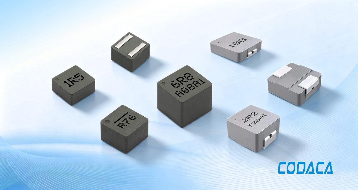
Codaca's proprietary molded power inductors leverage low-loss magnetic core materials and an advanced hot-pressing molding process, significantly reducing component footprint and power loss while enhancing overall operational reliability. Featuring a fully magnetically shielded design, they exhibit exceptionally low magnetic flux leakage, which prevents stray magnetic field coupling from interfering with sensitive Analog Front-End (AFE) voltage and current sensing signals. This ensures high SOC and SOH measurement accuracy, mitigates latent EMI-induced system faults, and elevates the electromagnetic compatibility (EMC) of the complete unit. Featuring an maximum operating temperature rating of up to 155°C and a peak power conversion efficiency of up to 98%, these power inductors effectively enhance overall BMS system reliability while maximizing DC-DC power conversion efficiency.
Recommended products: CSEG-H / CSEB-H / CSHB / CSAG
(3) Common Mode Choke
By selecting common-mode chokes engineered with high-impedance characteristics across target frequency bands, engineers can efficiently suppress common-mode noise and mitigate electromagnetic interference (EMI) impacts on BMS operational stability. Codaca provides a comprehensive range of common-mode choke solutions tailored to meet diverse customer application requirements.
Recommended products: TCAB / CSTP / CRHCM / CSUC
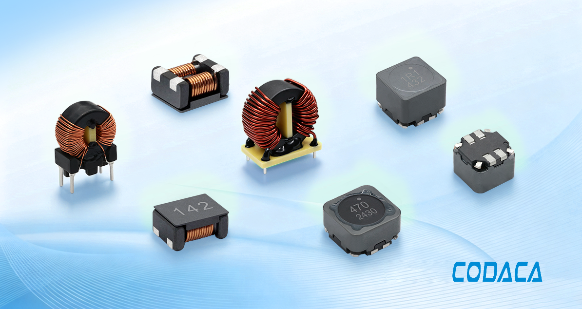
Driven by the surge in generative AI, data center backup energy storage systems are rapidly upgrading and iterating. As the core intelligence ensuring backup power safety, the Battery Management System (BMS) places increasingly stringent demands on the power density, long-term reliability, and EMI performance of magnetic components. With twenty-five years of deep specialization in power inductors, Codaca leverages material innovation and advanced manufacturing process iterations to deliver comprehensive, BMS-optimized inductor solutions for AI data center backup energy storage scenarios. Through high-reliability power magnetic components, Codaca safeguards the stable and continuous operation of global computing infrastructure.