With the rapid development of automotive electronics, industrial controls, and battery management systems (BMS), performance requirements for DC-DC converters are increasingly demanding. In the preceding section, we introduced the four-switch Buck-Boost converter, which exhibits significant advantages in applications prioritizing high conversion efficiency and high power density. In contrast, the focus of this chapter—the Single-Ended Primary-Inductor Converter (SEPIC) topology—demonstrates unique competitiveness in low-to-medium power applications where cost and reliability are paramount, such as automotive LED drivers, high-reliability instrument power supplies, and active balancing circuits in BMS. This is attributed to its low ripple and superior EMI characteristics driven by continuous input current, along with its simplified control structure and inherent short-circuit protection capabilities.
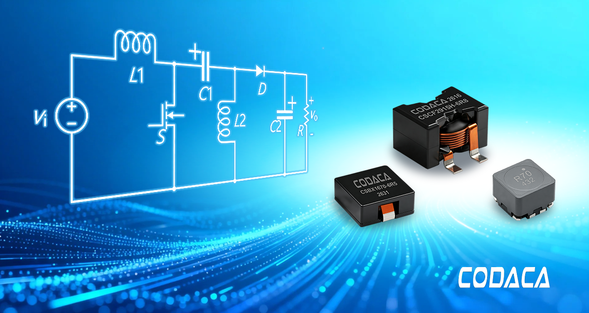
Accordingly, among the constituents of a SEPIC converter, the power inductor—typically configured using two uncoupled inductors or a coupled inductor—serves as a core component critical to ensuring high efficiency, stability, and reliable operation. It is not only responsible for energy storage and transfer—its inductance, coupling coefficient, current ripple, and other parameters directly affect the converter’s efficiency, electromagnetic compatibility, and long-term reliability. Whether the inductor parameters are properly designed and how well the component performs directly dictate the overall efficiency, loop stability, and long-term operational reliability of the converter.
1. Overview of the SEPIC Converter Operating Principle
The SEPIC converter is a classic DC-DC topology. In contrast to the non-inverting Buck-Boost converter, it evolves from the cascaded integration of a Boost step-up stage and a Buck step-down stage, utilizing either two discrete uncoupled inductors or a coupled inductor for energy storage and release.
Following cascading, the load and output capacitor of the Boost stage act as the input for the Buck stage. The combined network incorporates a pair of switching transistors, a pair of freewheeling diodes, and a pair of inductors. Following equivalent circuit transformation and commutation analysis—and after inverting the polarity of the downstream Buck stage—the active switching transistors and freewheeling diodes can be synchronously integrated, thereby deriving the Cuk converter topology. Because the downstream Buck stage is inverted to align with the freewheeling diode path, the Cuk converter inherently produces an inverted output voltage. By reversing this output polarity once more and rearranging the positions of the freewheeling diode and Buck inductor, the standard SEPIC topology is realized.
After the synchronous merging, switch S is the main power switch of the entire converter, driven by a PWM signal with duty cycle D (0<D<1). When S is on, the source stores energy in the input Boost-stage inductor L1, while the coupling capacitor C releases its stored energy to the output Buck-stage inductor L2. When S is off, diode D freewheels and conducts; L1 and L2 supply the load together, while the coupling capacitor C is charged by L1 through diode D, achieving balanced energy transfer. Diode D is a passive freewheeling element that conducts automatically during the off-time of S, providing a freewheeling path for the inductor current. Its conduction duty cycle is approximately (1-D); no external drive signal is required, as it is determined naturally by the circuit’s operating state.
The SEPIC converter is a step-up/step-down topology. Its voltage gain is the same as that of the traditional single-mode-controlled four-switch Buck-Boost: M=D/(1-D). However, unlike the four-switch Buck-Boost, the SEPIC’s output voltage polarity is the same as its input voltage (non-inverting output), whereas the four-switch Buck-Boost is inverting. By adjusting the duty cycle D, the output voltage can be made higher or lower than the input voltage: step-up when D>0.5, step-down when D<0.5.
A SEPIC converter incorporates two inductive windings. Given the tight PCB layout constraints and cost considerations in modern designs, utilizing a coupled inductor is generally the preferred approach.
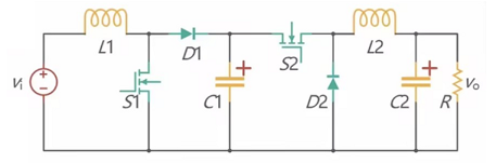
Figure 1 Boost-Buck Cascaded Converter
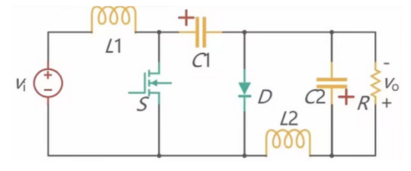
Figure 2 Cuk Converter
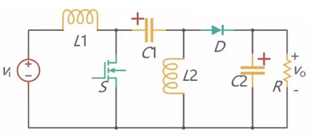
Figure 3 SEPIC Converter
2. Key Parameters of the Coupled Inductor
2.1 Inductance
The inductance value directly governs the converter's voltage conversion ratio, current ripple, and dynamic response: a larger inductance reduces current ripple, yielding smoother output voltage, higher efficiency, and superior stability, albeit at the expense of a slower dynamic response. Conversely, an excessively small inductance improves dynamic response speed, but induces larger current ripple, increases component power dissipation, degrades efficiency, and may even trigger system oscillations. Consequently, the inductor design must comprehensively balance operating modes, load characteristics, and target performance metrics.
2.2 Saturation Current
When the inductor current exceeds the linear region of the core, the magnetic flux saturates and the inductance drops sharply, losing its energy-storage and current-limiting capability. Inductor saturation causes loss of current control and a dramatic increase in ripple, subjecting the switch to overcurrent stress beyond its rating and even permanent damage.
Different core materials exhibit distinctly different inductance roll-off characteristics: small-air-gap drum-core inductors exhibit "hard saturation," with the inductance dropping sharply once the limit is exceeded (red curve); segmented-air-gap iron-powder-core inductors exhibit "soft saturation," with the inductance decreasing gradually as the current increases (blue curve).
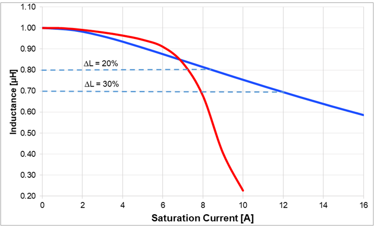
Figure 4 Hard saturation/soft saturation
2.3 AC/DC Resistance (ACR/DCR)
An inductor’s resistance includes DC resistance (DCR) and AC resistance (ACR). A lower DC resistance (DCR) minimizes conduction losses, thereby enhancing overall efficiency. Conversely, AC resistance (ACR) is governed by the skin effect: as operating frequency rises, the equivalent resistance increases, leading to a corresponding degradation in conversion efficiency. When selecting inductors, priority should be given to components featuring low DCR and optimized high-frequency characteristics to minimize power losses and maximize converter efficiency.
2.4 Operating Frequency
Increasing the switching frequency allows for smaller DC-DC converter footprints, enhanced power density, and faster dynamic response. However, higher frequencies exacerbate skin effect, proximity effect, and magnetic core losses, making high-frequency power dissipation and thermal management prominent challenges. Next-generation converters adopt variable-frequency control schemes, requiring inductors to maintain low losses across 200 kHz to 1 MHz or even wider frequency bands (e.g., up to 2.2 MHz). Consequently, inductors with excellent high-frequency characteristics—such as low-loss alloy powder cores or ferrites—should be selected, while establishing an optimal trade-off between power loss and physical size.
2.5 Coupling Coefficient
The coupling coefficient k represents the degree of magnetic flux coupling between the two windings, with a value between 0 and 1. The closer k is to 1, the tighter the coupling, the smaller the leakage inductance, and the more significant the ripple-steering effect, which can effectively reduce input/output ripple.
3. Inductor Selection Tool for DC/DC Converters
The DC-DC converter tool on Codaca's official website calculates the required inductance range based on user-selected converter parameters—including input/output voltages, switching frequency, ripple current, and topology. It then enables users to query component part numbers and conduct side-by-side performance comparison analyses. This tool recommends suitable inductor part numbers for synchronous and non-synchronous Buck/Boost converters, as well as SEPIC converters.
Power inductors serve as core components in DC-DC converters, executing critical functions in energy storage, energy release, and current ripple suppression. Their performance directly dictates the converter's efficiency, steady-state accuracy, and long-term operational reliability. Unlike dedicated Buck or Boost topologies, SEPIC converters must operate across a wide input and output voltage range. Consequently, the inductor must simultaneously withstand different current stresses and ripple conditions during both step-down and step-up modes, placing stringent requirements on the component's linearity, DC saturation characteristics, and high-frequency power dissipation. As power converter applications deepen across portable electronics, automotive power systems, and energy storage systems (ESS), power inductors are rapidly evolving toward higher power density, higher switching frequencies, and enhanced functional integration. To address these technological trends, Codaca Electronic enhances inductor performance through innovations in magnetic core material formulations, winding structure optimizations, and thermal management design. By continuously improving saturation current capabilities and reducing power dissipation, Codaca provides reliable support for the ongoing evolution of power converters, enabling more efficient and stable power conversion for wide-voltage-range applications in distributed energy and automotive electrification.