In the previous article, we used the metaphors of a "river of energy" and an "energy intermission" to explain the operating principles and design differences of inductors in Continuous Conduction Mode (CCM) and Discontinuous Conduction Mode (DCM). With its continuous current profile, CCM ensures smooth and highly efficient power delivery in high-power scenarios, including industrial and telecommunications applications. Conversely, DCM achieves an optimal balance between cost and efficiency in light-load consumer electronics applications by virtue of its periodic zeroing of freewheeling current. The choice between CCM and DCM is fundamentally a design trade-off to achieve the optimal solution across power density, dynamic response, and light-load efficiency.
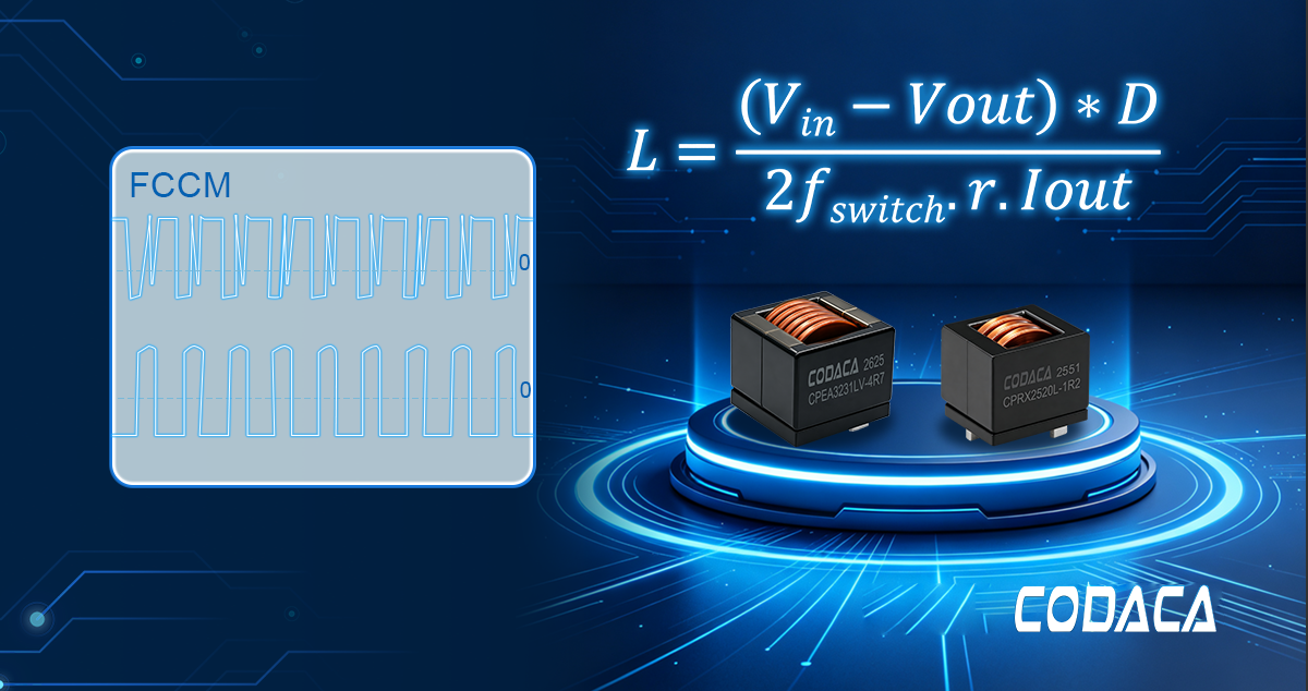
However, beyond the dichotomy of CCM and DCM, there exists a more rigid operating state—Forced Continuous Conduction Mode (FCCM). It breaks from the aforementioned operational logic: even under light-load or no-load conditions, active control mechanisms force the inductor current to remain continuous, allowing it to cross the zero axis and enter the negative region (i.e., reverse current flow).
This seemingly forced operation is not designed to improve efficiency; in fact, it exacts a significant efficiency penalty under light-load conditions. The underlying engineering rationale, however, lies in trading off light-load efficiency for a constant switching frequency, controllable output voltage ripple, and stable closed-loop dynamic response. This makes FCCM an irreplaceable specialized solution in high-end applications that are sensitive to high-frequency noise, require strict avoidance of frequency jitter falling into the audible spectrum, or impose extremely demanding load transient requirements.
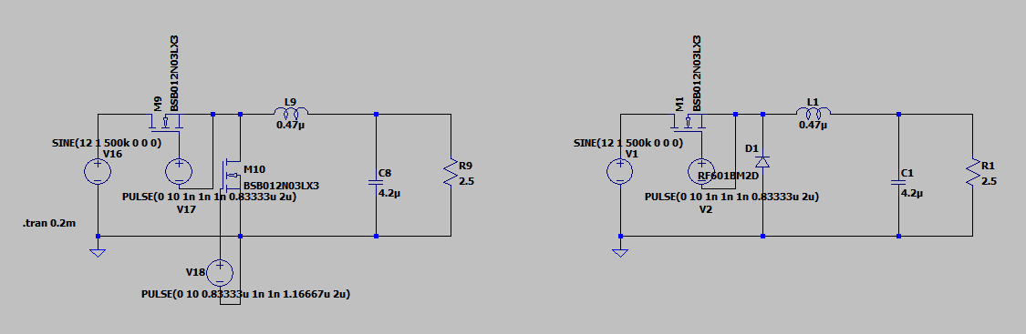
FCCM Mode
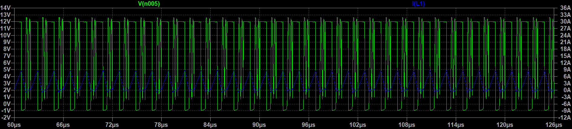
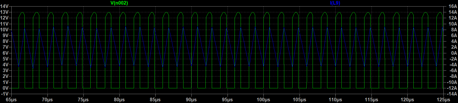
FCCM Waveforms
1、The Boundary Between "Continuous" and Discontinuous Conduction: The Failure of the Critical Value
In our previous discussions regarding CCM and DCM, we established a clear design criterion: whether a power converter operates in continuous or discontinuous mode fundamentally depends on whether the inductor current drops to zero at the end of each switching period. When the minimum inductor current drops to exactly zero, the converter reaches a critical boundary state. This critical point is determined by the boundary inductance (Lb): when the actual inductance L > Lb, the system operates in CCM; when L < Lb, it enters DCM. This framework is simple yet effective, and serves as the theoretical basis for the vast majority of power supply designs.
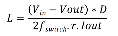
However, when we extend our focus to FCCM, the natural boundary condition of 'whether the inductor current decays to zero' is artificially eliminated.Even if the actual inductance is far below the theoretical boundary inductance Lb, so that the load would naturally fall into the DCM region and an "energy gap" should appear, the control loop still forces the switch to operate throughout the entire cycle, driving the inductor current across the zero axis into negative territory. At this point, the operating mode is no longer decided by the natural relationship between L and Lb, but is dominated by the control strategy:
(1)When the system is configured for FCCM, the inductor current is forcibly maintained in a continuous state—even extending into continuous negative current flow—regardless of the relationship between the actual inductance L and the critical boundary inductance Lb. At this point, Lb loses its significance as a 'natural boundary.' Instead, designers must focus on another critical metric: peak negative current. The saturation current (Isat) margin of the inductor is no longer dictated solely by the peak positive current, but must also accommodate the additional magnetic stress induced by reverse current flow.
(2)When the system operates in DCM, the inductor current follows its natural course, returning to zero in every cycle and remaining there for an interval. In this case, the condition L < Lb still holds, and the advantages of simple control and high light-load efficiency are preserved.
In other words, in the context of FCCM, this ‘watershed’ is artificially leveled by the control strategy. What designers face is no longer the binary choice of ‘a large inductor or a small inductor’, but the top-level decision of ‘whether to trade light-load efficiency for constant frequency and fast dynamic response’. Once FCCM is chosen, the focus of inductor selection shifts from ‘whether the boundary condition is met’ to ‘whether it can withstand bidirectional current stress and additional core losses’, placing higher demands on the inductor’s anti-saturation capability.
2、Selecting a Power Inductor: Parameters Affected by FCCM
1. AC Resistance (ACR)
AC resistance is the resistance presented by the inductor winding under AC conditions, encompassing the combined equivalent impedance of the skin effect and the proximity effect. The higher the switching frequency, the more pronounced these effects become, and the AC impedance can far exceed the DC resistance, causing a substantial increase in high-frequency winding losses. In FCCM mode, the inductor always operates at a fixed switching frequency, so the losses caused by AC resistance persist even at light load, affecting system efficiency. Therefore, in FCCM designs, priority should be given to inductors using flat-wire winding construction to reduce AC resistance and improve light-load efficiency. Codaca high-current inductors adopt a flat-wire winding design, effectively suppressing the growth of AC resistance at high frequencies and providing an efficient and reliable solution for FCCM applications.
2.High-Frequency Core Loss
Core loss refers to the power dissipation induced within the magnetic core material by an alternating magnetic field, driven by hysteresis and eddy current effects. As the switching frequency increases, the core loss increases accordingly. Under Forced Continuous Conduction Mode (FCCM), core loss does not decrease with reduced output power during light-load operation. Instead, due to the continuous presence of reactive circulating current, it becomes a dominant heat source within the system. Consequently, FCCM designs should prioritize magnetic powder core materials that exhibit low loss characteristics at high operating frequencies. Codaca high-current inductors utilize low-loss magnetic powder core materials, effectively suppressing high-frequency hysteresis and eddy current losses. This keeps light-load temperature rise within a manageable range, ensuring long-term, reliable system operation.
3.Inductance Stability
Inductance stability refers to the capability of an inductor to maintain its nominal inductance under actual operating conditions, including DC bias, ambient temperature, and aging. Under typical conditions in CCM or DCM, moderate inductance variations can be tolerated through loop compensation, preserving steady-state circuit operation. In FCCM mode, however, the inductor operates continuously at a fixed switching frequency, and drift in the L value directly causes the actual switching frequency to deviate from the designed value, which in turn affects the output ripple, loop stability, and even system EMI characteristics.
3、Codaca’s Solutions for Converters
Through in-house research and technological innovation, Codaca delivers differentiated inductor solutions tailored for DC-DC converters operating in various modes. In light of the bidirectional flux excitation stress and elevated core dissipation induced by zero-crossing inductor currents under FCCM, conventional component selection guidelines prove insufficient. Codaca's proprietary high-current magnetic powder core inductors, backed by their outstanding DC bias performance and high saturation current (Isat) capability, effectively withstand the impacts of peak currents—particularly negative peak currents—under FCCM operating conditions, mitigating thermal failure risks associated with core saturation. At the same time, its low-loss magnetic core characteristics effectively mitigate core losses (iron losses) induced by continuous high-frequency ripple currents, thereby preserving system conversion efficiency even under high-intensity circulating current conditions.
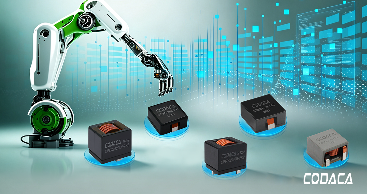
Whether targeting performance-driven FCCM, high-power-density CCM, or light-load efficiency in DCM, Codaca delivers a comprehensive portfolio of inductor solutions across all application scenarios—such as industrial control, automotive electronics, renewable energy storage, and data centers. This empowers engineers to strike a precise balance between high performance and green, low-carbon design goals.