In switched-mode power supply (SMPS) topologies such as buck and boost converters, the inductor serves as the core energy storage element. Its operating mode directly dictates the power rating, conversion efficiency, and overall physical size of the power supply. Continuous Conduction Mode (CCM) and Discontinuous Conduction Mode (DCM) represent the two fundamental operating regimes. Dedicated design optimization for either mode is never arbitrary, rather, it is intrinsically tied to the specific performance demands of the target end applications.
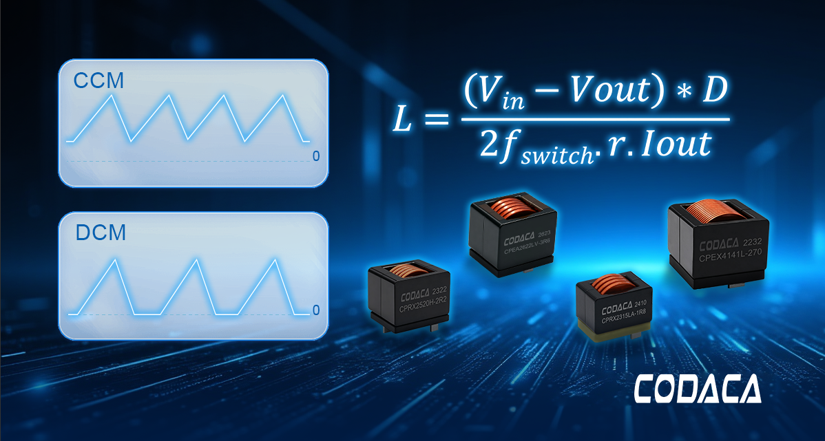
1-The Two Primary Operating Modes of Switched-Mode Power Supplies
In Continuous Conduction Mode (CCM), the inductor current flows continuously throughout the entire switching cycle while remaining strictly within the designed parameters, akin to a steady 'river of energy.' Due to its low current ripple and stable output characteristics, this mode significantly reduces conduction losses and output capacitor stress. Consequently, it is ideal for high-power applications across industrial, telecommunications, and automotive sectors that demand stringent efficiency, power density, and dynamic response.
In Discontinuous Conduction Mode (DCM), the inductor current drops to zero within each switching cycle, meaning that no current flows through the inductor for a portion of the period, thereby creating a distinct 'energy intermission' phase. This allows the converter to achieve higher conversion efficiency under light-load conditions, alongside the inherent advantage of zero-current switching (ZCS) turn-off for the diode, thereby simplifying the overall system architecture. Consequently, DCM is widely utilized in small-to-medium power consumer applications—such as mobile fast chargers and power adapters—where cost sensitivity and light-load efficiency are paramount.
If an improper selection occurs—such as specifying a DCM-optimized inductor for an industrial high-power CCM application—it may result in core saturation, thermal runaway, and ultimate component failure.
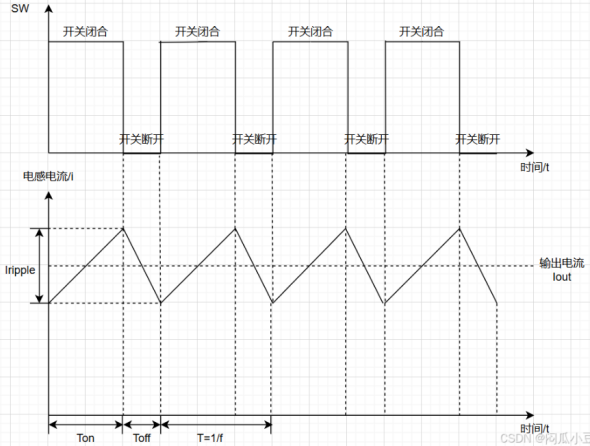
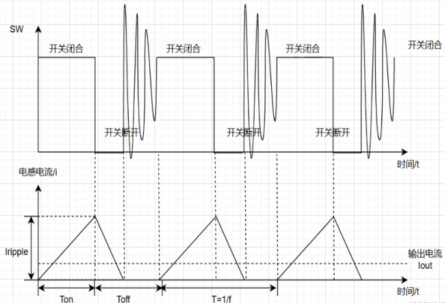
CCM Mode DCM Mode
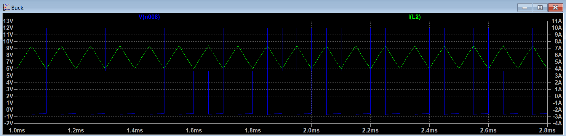
CCM Waveforms
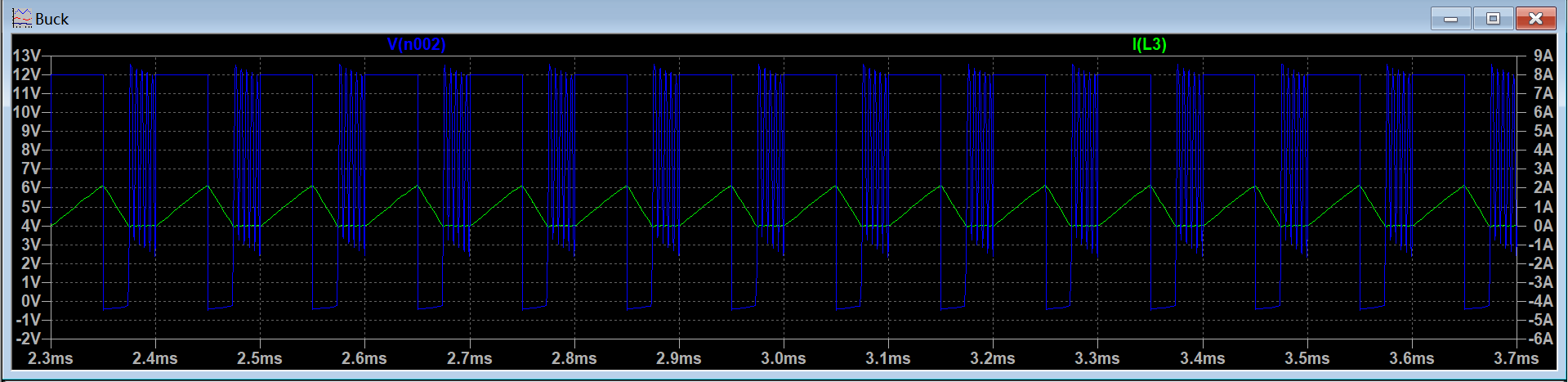
DCM Waveforms
2、The CCM/DCM Boundary: Calculating Critical Parameters
Whether a power converter operates in Continuous Conduction Mode (CCM) or Discontinuous Conduction Mode (DCM) fundamentally hinges on whether the inductor current decays to zero by the end of each switching cycle. If the minimum inductor current reaches exactly zero, the converter enters the critical boundary state.
This boundary point is determined by a critical parameter: the boundary inductance (Lb). Derived from the fundamental volt-second balance principle of the converter topology, its calculation formula clearly reveals the underlying constraints among the system parameters:
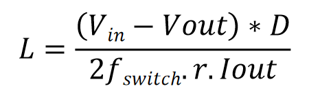
(1)When the actual inductance L > Lb, the inductor has relatively strong "energy-storage capability." At the given load current (Io), the current will not decay to zero within one cycle, so the system operates stably in CCM. For industrial applications pursuing high efficiency and high power, designers usually ensure operation in CCM across the full load range to reduce current ripple and device stress.
(2)When the actual inductance L < Lb, the inductor’s "energy-storage capability" is relatively weak: the current quickly returns to zero and stays there for an "idle interval," so the system operates stably in DCM. For consumer applications that prioritize light-load efficiency and compact size, designers may accept or deliberately allow the system to enter DCM under typical load conditions to simplify the control and optimize partial-load efficiency.
3、Inductor Selection: Key Parameters
3-1 Saturation Current
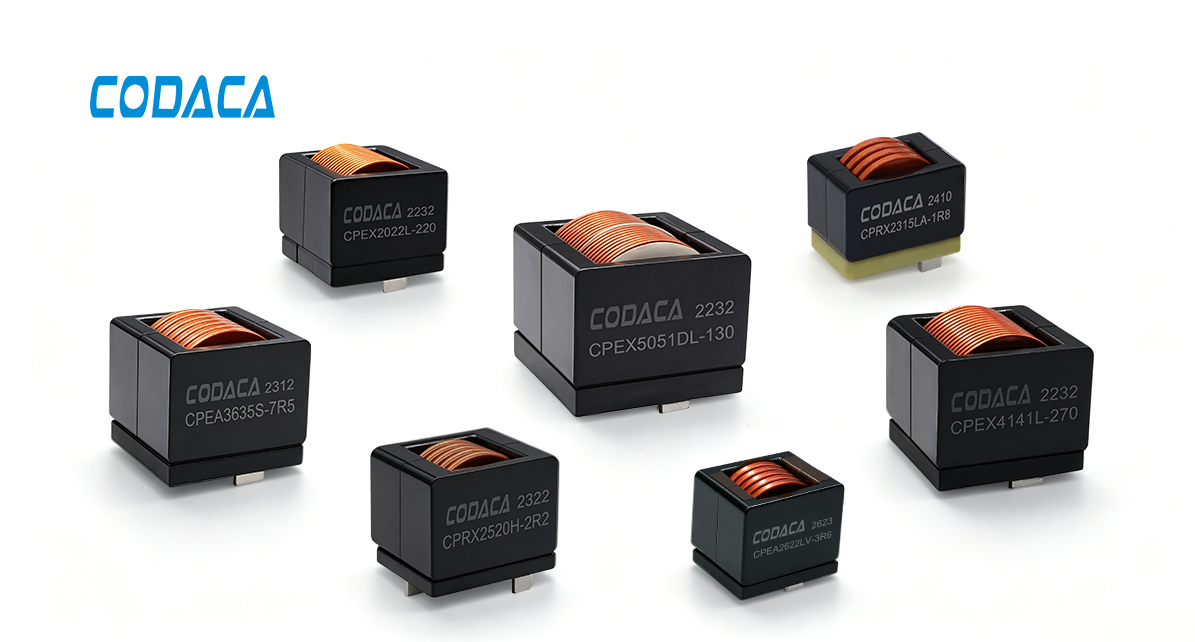
When the inductor current becomes excessively high and the magnetic core flux density reaches its saturation limit, the inductor enters magnetic saturation, causing its inductance value to drop precipitously. Particularly in high-power industrial CCM converters, core saturation triggers an uncontrollable current spike and a massive increase in ripple current. This runaway condition induces overcurrent stress on power switching devices, leading to catastrophic semiconductor failure and severely jeopardizing system operation. To prevent magnetic saturation, engineers must carefully optimize the core material and dimensions to ensure that the inductor does not saturate under the maximum operating current of the converter. Additionally, techniques such as introducing an air gap can be employed to extend the linear operating range of the inductance, thereby enhancing overall converter reliability. Codaca has independently developed multiple series of high-current inductors based on metal powder cores, utilizing a patented powder formulation to significantly enhance the inductor's saturation characteristics.
3-2 DC Resistance (DCR)
DC resistance (DCR) refers to the internal resistance of the inductor's winding coil under DC conditions. A lower DCR results in reduced power dissipation when current flows through the inductor, thereby improving overall system efficiency.
When selecting an inductor, priority should be given to products featuring low DCR characteristics to minimize conduction losses and boost converter efficiency.
3-3 Operating Frequency
Increasing the converter's switching frequency allows for smaller passive components—such as inductors and capacitors—thereby enhancing power density and dynamic response performance. At high switching frequencies, however, the detrimental impact of parasitic parameters intensifies, with skin and proximity effects driving a substantial surge in inductor losses. Conventional magnetic materials may prove inadequate, thereby worsening core loss-induced thermal dissipation issues. Consequently, specifying high-frequency, low-loss inductors is vital to guaranteeing stable and reliable system operation.
3-4 Operating Temperature
Power inductors must exhibit robust physical properties and strong environmental adaptability. The size and weight of inductors must satisfy the compact design requirements of residential energy storage equipment. Under harsh operating environments characterized by elevated temperatures and high humidity, inductors must maintain stable performance. Magnetic core materials should exhibit minimal susceptibility to temperature and humidity fluctuations, while offering superior heat dissipation along with robust resistance to moisture, mold, and corrosion. When selecting components, priority should be given to high-current magnetic powder core products that feature high operating temperature ratings and minimal temperature sensitivity in their DC bias characteristics.
4、Codaca Provides a Diverse Portfolio of High-Reliability Inductor Solutions for DC-DC Converters
Through proprietary R&D and continuous technological innovation, Codaca provides a diverse range of tailored inductor solutions for DC-DC converter systems, supporting green and low-carbon development. The company offers multiple product series—including high-current inductors and integrated molded inductors—delivering flexible electrical parameters and package footprints to meet the demanding high-performance requirements of power converter applications.
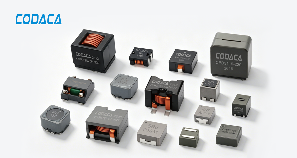
Codaca's proprietary high-current magnetic powder core inductors feature high saturation current, low losses, high conversion efficiency, and elevated operating temperature capabilities—meeting the high operational current, low power dissipation, and high power density requirements of industrial Continuous Conduction Mode (CCM) DC-DC converter systems. Meanwhile, compact molded inductors featuring magnetically shielded structures offer low losses, high efficiency, and a broad operational frequency bandwidth, making them well-suited for cost-effective and low-power-consumption converter designs.