As the requirements for DCR in high-performance DC-DC converters and AI power modules continue to drop to the milliohm or even microohm level, the traditional two-wire method introduces errors that are too large, making it necessary to adopt a four-wire (Kelvin) connection method for measurement. Many engineers believe that DCR measurement is simple, thinking it can be done by simply clamping the component with the test leads of a multimeter or an LCR meter. However, in actual production, issues frequently arise, such as: inconsistent readings across multiple instruments for the same inductor, data fluctuations due to varying pressure on the test leads, and severely inflated measurement data for low-inductance inductors. Let us explore the underlying causes below.
I. Understanding the Essence of Inductor DCR and Measurement Difficulties
The DC resistance (DCR) of an inductor refers to the pure resistive component presented by the inductor winding under DC excitation, which originates from the intrinsic resistance of the copper wire used to wind the inductor. This parameter directly determines power conversion efficiency, heat dissipation, and the long-term reliability of the power system.
The core technical difficulty in accurately measuring DCR lies in the fact that the DCR of common inductor windings is typically between a few milliohms and several hundred milliohms. When the resistance to be measured drops to the milliohm level, the resistance of the test leads themselves(typically 0.1Ω~0.5Ω)and the probe contact resistance (a few milliohms to tens of milliohms) in the traditional two-wire measurement are already in the same order of magnitude as the resistance under test. Consequently, the measured value will severely deviate from the true value.
II. Kelvin Four-Wire Method—The Fundamental Solution to Eliminate Lead Errors
The standard solution for low-resistance measurement is the Kelvin Four-Wire Connection. This technique was invented by Lord William Thomson Kelvin in 1861 and remains the benchmark method for precision low-resistance measurements today.
(1)Why the Two-Wire Method is Infeasible
In a common two-wire measurement, the current excitation loop and the voltage detection loop share the same pair of wires. The resistance value measured by the meter is:
R_measured = R_DUT + 2 × (R_lead + R_contact)
Where R_leadis the resistance of a single test lead (typically in the to hundreds of range), and R_contact is the contact resistance between the probe and the test point ( range). When R_DUT is only a few milliohms, the error introduced by the lead and contact resistances can be up to tens of times the actual value.
(2)Core Principle of the Kelvin Four-Wire Method
The Kelvin four-wire method addresses this issue by physically separating the current path from the voltage detection path. The four wires are divided into two pairs, each serving a distinct purpose:
Force lines (Current excitation lines, 2 wires): Apply a known, constant DC current to the inductor under test. Voltage drops may exist across this current loop, but the lead resistance and contact resistance do not affect the accuracy of the measurement results.
Sense lines (Voltage detection lines, 2 wires): Independently measure the true voltage drop across both ends of the inductor (rather than at the test fixture terminals). Since the input impedance of the voltage detection loop is extremely high (modern test instruments typically>1GΩ),the current flowing through the Sense lines approaches zero. Thus, lead resistance and contact resistance do not produce any significant voltage drop on the detection lines.
According to Ohm's law, the DCR of the inductor can be calculated by the following formula:
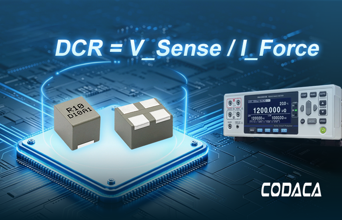
DCR = V_Sense / I_Force
V_Sense is the voltage across the inductor directly measured by the Sense lines without containing any lead voltage drop, and I_Force is a known constant current, dividing the two yields the true DC resistance value, which is entirely independent of all contact and lead resistances in the external loop.
(3)Four-Wire Measurement Precautions
1.Independent Contact: The four wires must separately contact four distinct points on the two electrodes of the inductor. In actual fixtures, each electrode is contacted by two probes simultaneously (Force + Sense), but the two are not connected inside the fixture; they only converge at the contact pad.
2.Probe Cleanliness: Pad oxidation or residual flux can create unstable contact resistance. Although this does not affect the Sense lines, it may cause instability in the current loop or saturate the constant current source. Before measurement, clean the pads with anhydrous alcohol or gently wipe them with an eraser.
III. Comparative Verification of Test Data
Taking the Molding Power Choke for AI applications from CODACA's official website as an example, the model CSHN100760-56NN was selected for a comparative test using three common instruments on the market: a DC resistance tester, a multimeter, and an LCR. bridge.
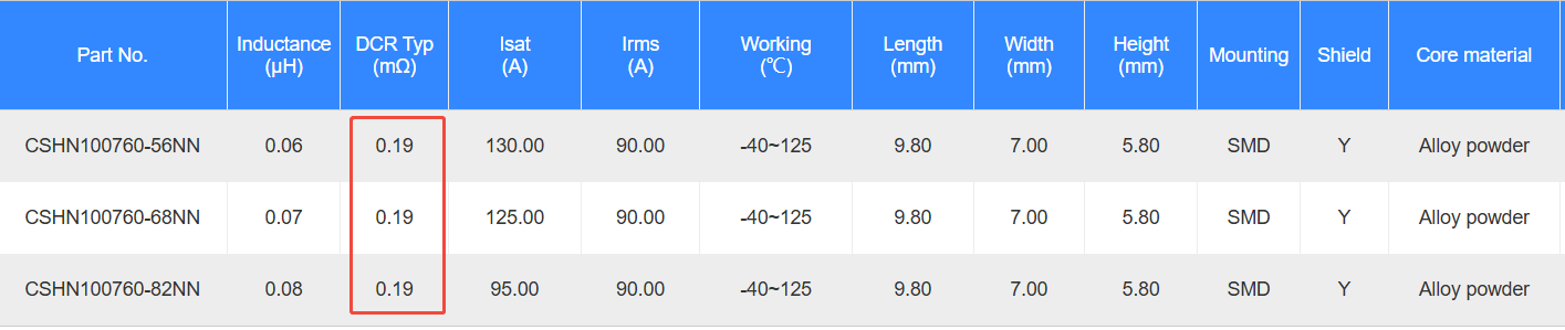
Figure 1. The Molding Power Choke CSHN100760-56NN Electrical Characteristics
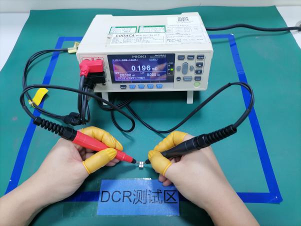
Figure 2. DC Resistance Tester (Kelvin Four-Wire Method):DCR Test Zone
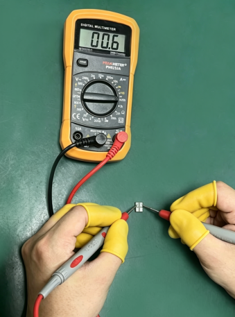
Figure 3. Multimeter (Two-Wire Method)
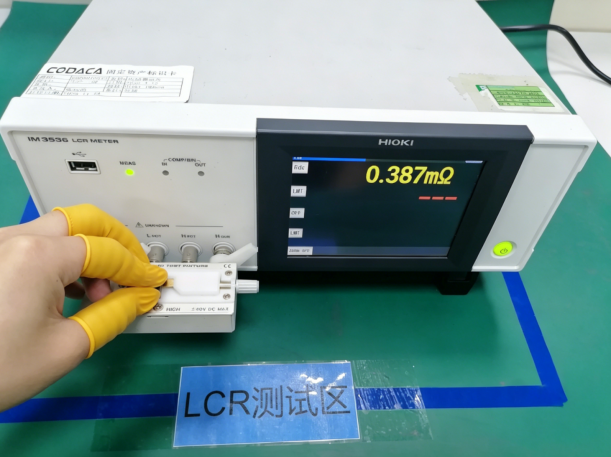
Figure 4. LCR Bridge (Fixture Testing):LCR Test Zone
As shown in Figure 1, the specifications sheet for CSHN100760-56NN defines the DCR as 0.22mΩ Max.,The test result using the DC resistance tester (Kelvin four-wire method) is 0.196mΩ,which meets the requirements of the specification sheet, with the actual measurement result shown in Figure 2. When using a common multimeter (two-wire method) with the range adjusted to the basic resistance measurement range of 200Ω,which provides a resolution of 0.1Ω,the test result is 600mΩ,which fails to meet the specification requirements, as shown in Figure 3. When using the LCR bridge (fixture testing) adjusted to the DCR range followed by zero-correction, the test result is 0.387mΩwhich is closer to the target value but still fails to meet the specification requirements.
Consequently, to ensure the accuracy of the test results, a dedicated DC resistance tester (Kelvin four-wire method) is preferred when performing DCR tests on magnetic components such as inductors.