With the rapid development of portable electronic devices, automotive power systems, and energy-storage BMS applications, scenarios requiring wide input and wide output voltages are becoming increasingly common. Against this backdrop, the Buck-Boost circuit has become a core topology for flexible input-output adaptation and stable power transmission, owing to its inherent bidirectional step-up/step-down capability—making its importance self-evident. Among the components of a Buck-Boost circuit, the power inductor is an extremely critical element. It not only stores and releases energy but also smooths the current and suppresses ripple. Whether the inductor parameters are designed reasonably and how well the inductor performs directly affect the overall efficiency, stability, and long-term reliability of the converter.
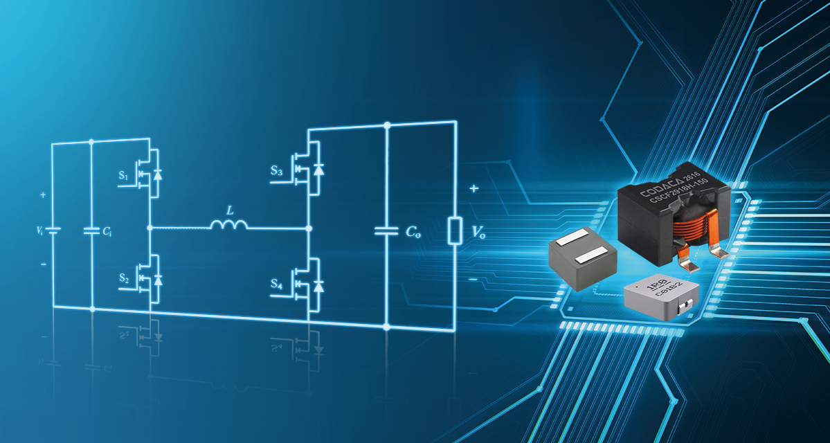
1.Buck-Boost Converter Operating Principle Overview
The four-switch buck-boost converter is a classic DC-DC topology that combines the features of Buck (step-down) and Boost (step-up) converters; it further evolved from the cascaded topology of a Buck step-down converter and a Boost step-up converter, with both sharing the same power inductor.
The four switches on the two bridge arms of the converter each take on different tasks: Switches S1 and S2 on the same bridge arm form the Buck stage, where the high-side switch S1 acts as the primary control switch with a duty cycle of D1, while S2 operates with a complementary duty cycle of (1 - D1).Switches S3 and S4 on the same bridge arm form the Boost stage, where the low-side switch S3 acts as the primary control switch with a duty cycle of D3, while S4 operates with a complementary duty cycle of (1 - D3).The overall voltage gain of the converter is expressed as M = D1 / (1 - D3).
Unlike traditional single-switch Buck-Boost converters, the four-switch synchronous Buck-Boost converter achieves non-inverting output voltage (same polarity as the input) through a control scheme where S1 and S3 conduct diagonally in sync, while S2 and S4 provide complementary freewheeling. This topology enables seamless transition across three operating modes: Vin > Vout (step-down mode), Vin ≈ Vout (Buck-Boost transition mode), and Vin < Vout (step-up mode). Consequently, it is widely utilized in wide-voltage applications with overlapping input and output voltage ranges.
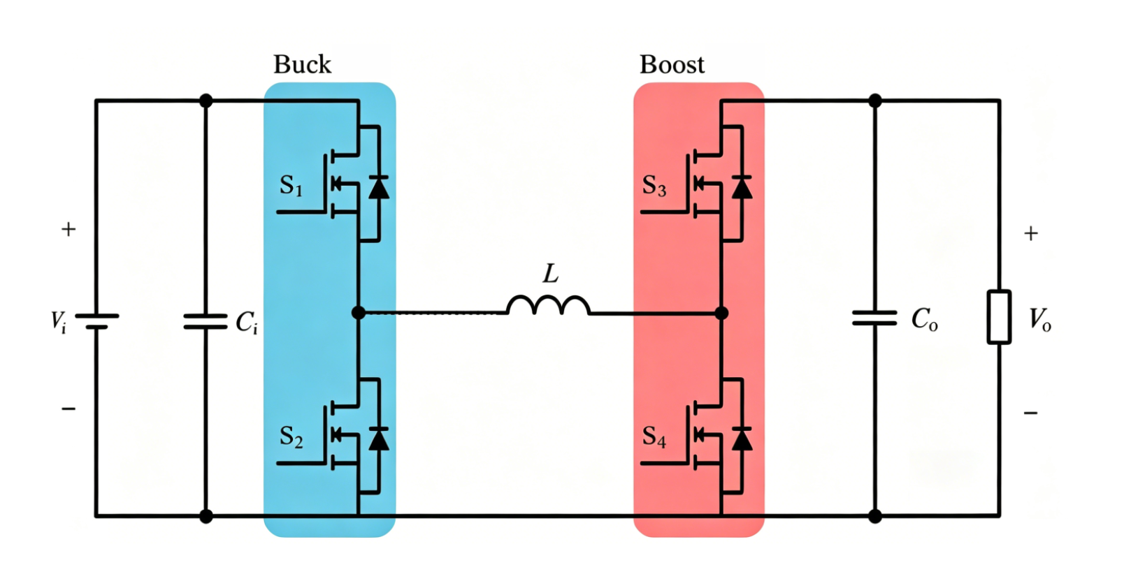
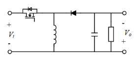
Figure 1 Four-Switch Buck-Boost Figure 2 Sing-Mode Buck-Boost
A four-switch Buck-Boost converter contains only one inductor, yet that inductor operates in two distinct phases. When the main switch of the Buck stage (S1) is on, current flows through the loop formed by the positive input terminal → S1 → inductor L → S4 → load → ground (GND). The inductor current ramps up, and energy is stored in the inductor as magnetic energy. When the switch turns off, the inductor current cannot change instantaneously, so the stored magnetic energy is released. With the main switch of the Boost stage (S3) conducting, a freewheeling loop forms: inductor L → load → S2 → ground (GND) → S3 → inductor L. This loop keeps the load current continuous.This 'charge-and-discharge' mechanism represents the fundamental operating principle of all switching power supplies, where the inductor's charging and discharging loops dynamically alternate in sync with the switching states of the high-side and low-side switches.
In Buck mode, the inductor charges via the S1-L-S2 path, whereas in Boost mode, it stores energy via the S3-L-S4 path. Because Buck-Boost converters typically accommodate a wide input voltage range, the inductor ripple current often varies significantly. Since high ripple current leads to elevated power losses, reducing the inductor's DCR and increasing the switching frequency can effectively constrain losses under large ripple conditions.
2.Impact of the Power Inductor on the Buck-Boost Converter
As previously described, the inductor in a Buck-Boost converter experiences significantly higher current stress than in standalone Buck or Boost topologies. Proper inductor selection requires quantifying its impact across four key dimensions: inductance (L), saturation current (Isat), AC/DC resistance (ACR/DCR), and switching frequency (f), evaluating the specific mechanics of each parameter on overall converter performance.
01-Inductance
The inductance value directly impacts the converter's operating mode, current ripple, and dynamic response speed. A larger inductance results in lower current ripple, smoothing the output voltage and enhancing efficiency and stability; however, it slows down dynamic response, preventing rapid output voltage adjustment during sudden load transients. Conversely, a smaller inductance accelerates dynamic response but yields larger current ripple. This increases power device losses, degrades efficiency, and may even trigger circuit oscillation, compromising system operation. Practical designs require a balanced approach, precisely selecting the inductance value based on operating modes, load characteristics, and performance requirements.
02-Saturation Current
When the inductor current rises beyond the magnetic core material's linear operating region, the flux density reaches saturation, causing the inductance to drop sharply. As a result, the inductor loses its ability to effectively store energy and limit current. In a Buck-Boost converter, because the full-power path relies solely on a single inductor for energy transfer, inductor saturation directly triggers runaway current and a surge in ripple current. This subjects the power switches to excessive overcurrent stress, ultimately leading to permanent device failure.
3-AC/DC Resistance (ACR/DCR)
The resistance of an inductor comprises DC resistance (DCR) and AC resistance (ACR). DCR represents the internal resistance of the winding coil under DC conditions. A lower DCR reduces power dissipation when current flows through the inductor, thereby contributing to higher overall efficiency. ACR refers to the equivalent AC resistance of the inductor at a specific switching frequency, reflecting the combined effects of the skin effect, proximity effect, and core loss in the winding. As the frequency increases, the rise in ACR becomes significantly more pronounced.
When selecting an inductor, priority should be given to products with low DCR and high-frequency characteristics matched to the system, thereby minimizing losses and enhancing converter efficiency.
04-Operating Frequency
Increasing the switching frequency is an effective approach to downsizing passive components in a Buck-Boost converter, boosting power density, and accelerating dynamic response speed. However, elevating the frequency introduces a series of high-frequency parasitic effects. As the operating frequency rises, the skin and proximity effects in the inductor intensify, significantly increasing the winding's AC resistance and resulting in a steep surge in high-frequency losses. Simultaneously, high-frequency core losses (hysteresis loss and eddy current loss) in the magnetic material escalate, making thermal management and temperature rise issues significantly more prominent.
Next-generation power management converters no longer rely solely on fixed-frequency operation; instead, they dynamically adjust the operating frequency in response to load variations to maintain high efficiency across the entire load range. This requires magnetic materials to sustain low loss across the entire frequency range from 200 kHz to 1 MHz—and even higher—rather than merely performing well at a single optimal frequency point. Therefore, designers should select inductors with superior high-frequency characteristics—such as low-loss metal powder cores or ferrite materials—and strike an optimal trade-off between power loss and physical size to ensure highly efficient and stable system operation across all frequency ranges.
3.Recommended Power Inductors for Buck-Boost Converters
As previously discussed, in high-current stress and wide-operating-condition applications like four-switch Buck-Boost converters, adopting a flat-wire, high-current discrete inductor solution achieves a superior overall balance across key dimensions—including DCR losses, high-frequency ACR losses, saturation surge tolerance, and physical footprint. This makes it an ideal choice for enhancing overall converter efficiency and long-term reliability.
01-Compact High-Current Power Inductor CSBA
The compact, high-current CSBA series utilizes Codaca's proprietary low-loss core material, featuring excellent soft saturation characteristics and extremely low DC resistance (DCR). Its magnetically shielded construction delivers outstanding electromagnetic compatibility (EMC), significantly suppressing high-frequency electromagnetic interference (EMI) radiation. Designed with a low-profile footprint suitable for high-density surface mounting, the CSBA series is an ideal low-profile inductor optimized for Gallium Nitride (GaN) circuit designs.
The CSBA series can be widely deployed in core modules such as DC-DC converters and switching regulators for Gallium Nitride (GaN) power supplies. In applications like AI server power supplies and renewable energy equipment, its high-current handling capability and superior high-frequency adaptability support high-power-density power designs while ensuring long-term stable system operation.
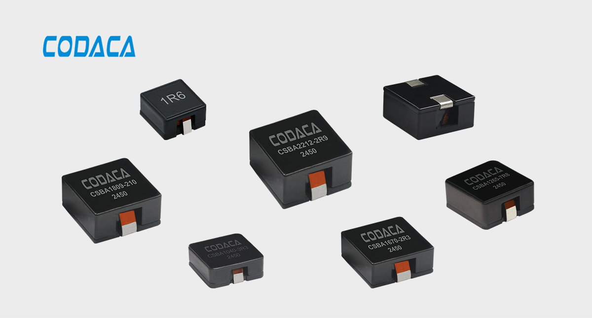
Compact High Current Power Inductor CSBA
02-Super High Current Power Inductor CSCFA
The Super High Current Power Inductor CSCFA series utilizes Codaca's proprietary low-loss core material, featuring low power loss, high efficiency, a broad operating frequency range, and wide application versatility.Featuring a flat-wire winding design, the CSCFA series delivers superior thermal dissipation and low temperature rise. Its exceptional DC bias capability allows it to handle transient high peak currents smoothly. Furthermore, the wide closed magnetic circuit design effectively suppresses electromagnetic radiation and conducted interference, boosting electromagnetic compatibility (EMC). The series is widely applicable to fields such as renewable energy, industrial control, high-current power supplies and battery management systems (BMS), distributed power DC-DC converters, and artificial intelligence.
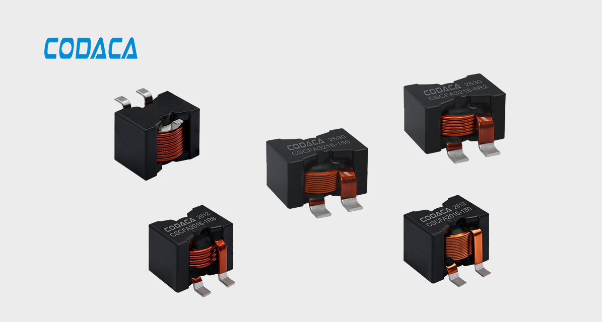
Super High Current Power Inductor CSCFA
03-Super High Current Power Inductor CPCFA
The Super High Current Power Inductor CPCFA series utilizes a flat-wire winding design, featuring low impedance, high saturation current, and low temperature rise. Its closed magnetic circuit design effectively suppresses electromagnetic radiation and conducted interference, boosting electromagnetic compatibility (EMC). Highly stable, the inductance and DC bias capability of this series remain virtually unaffected by temperature fluctuations. The CPCFA series is widely applicable to DC-DC converters, high-current switching regulators, photovoltaic (PV) inverters, industrial automation, renewable energy systems, and other fields.
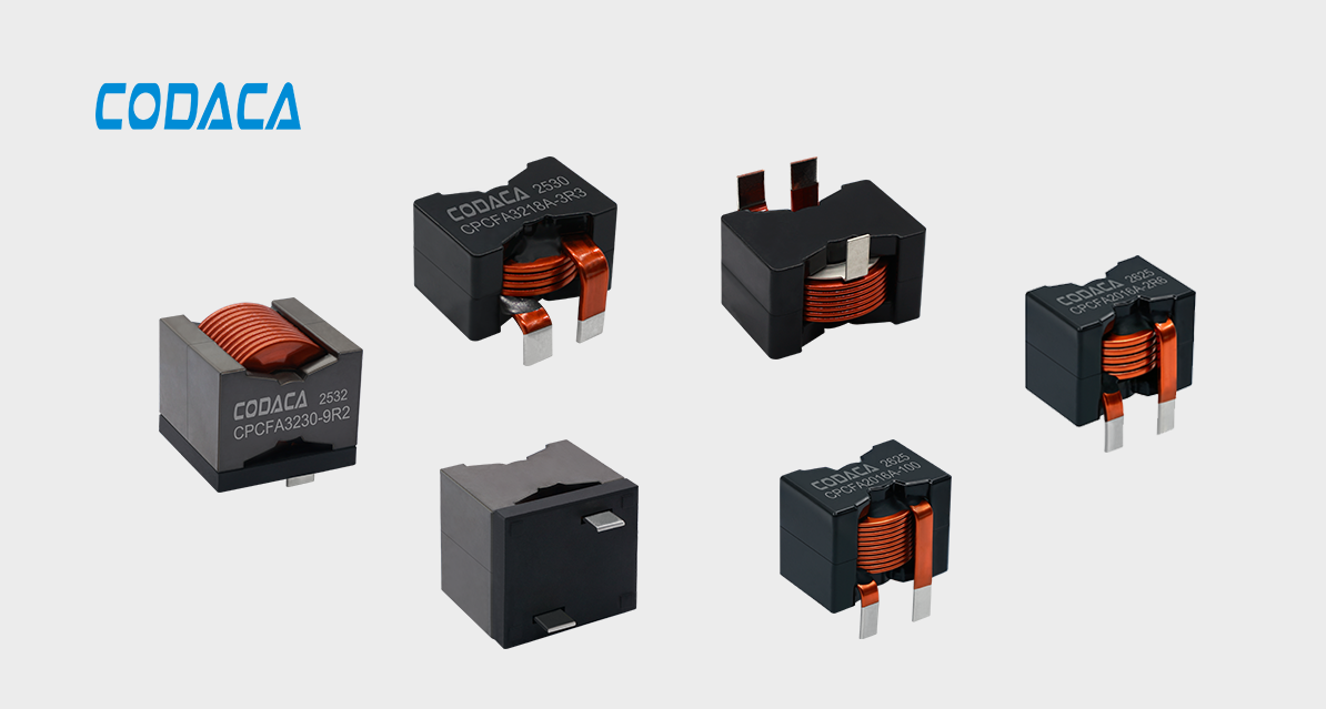
Super High Current Power Inductor CPCFA
4.DC/DC Converter Inductor Selection Tool
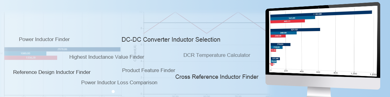
When designing a DC-DC converter, engineers are often confused by the wide variety of inductor types and parameters. The Codaca DC-DC converter selection tool greatly improves selection efficiency. By specifying converter parameters such as input/output voltage, switching frequency, ripple current, and topology, it calculates the required inductance range, looks up device part numbers, and provides performance comparison analysis. The tool can recommend suitable inductor materials for synchronous and non-synchronous step-up/step-down converters as well as SEPIC converters.
As a core component of the Buck-Boost converter, the power inductor plays a critical role in energy storage, energy release, and current ripple suppression. Its performance directly determines the converter's efficiency, steady-state accuracy, and long-term reliability. Unlike dedicated buck or boost topologies, a Buck-Boost converter must operate across a wide input and output voltage range. The inductor must simultaneously adapt to different current stresses and ripple conditions in both buck and boost modes, imposing stringent requirements on the inductor's linearity, saturation characteristics, and high-frequency losses.
As Buck-Boost converters are increasingly deployed across portable electronics, automotive power systems, and energy storage systems (ESS), inductors are evolving toward higher power density, higher operating frequencies, and greater integration. In response to these trends, Codaca Electronic continuously enhances the saturation current and loss characteristics of its inductor products by advancing core material formulations, optimizing winding structures, and refining thermal management design. These innovations provide robust support for the performance evolution of Buck-Boost converters, empowering wide-voltage-range scenarios to achieve higher efficiency and greater stability in distributed energy systems and automotive electrification.